5.14
ROSTA
Motorbases in customized design
for special applications
Fan drive in heat exchanger with vertically
installed motor on MB 50, special
The MB 50 had been equipped with an additional
bronze glide bearing to assure the axial position
of the motor on the elastic ROSTA element.
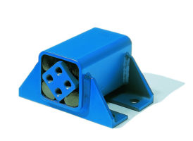
Installation of cooling compressors in
busses on MB 45 special, equipped with
heat-resistant elastic inserts Rubmix 40
In this specific application, the ROSTA Motorbase is fulfilling
two main functions: keeps the belt tightened between Diesel-
engine and cooling compressor, does prevent the transmission
of compressor vibrations into the bus chassis.
ROSTA
Calculation:
Tensioning Motorbase
D, R
diameter and radius of the driven puley, D=
280 mm
d, r
diameter and radius of the drive puley (above the ROSTA element), d=
190 mm
n
speed of the drive puley (above the ROSTA element)
2040 rpm
P
power of the motor above the ROSTA element
45 kW
i
factor of the overturning torque (during start of the motor)
2.3 -
Pi
max. required power during the start process of the motor = P * i
103.5 kW
A
distance of the puleys
calculation 1
mm
X
horizontal distance of the puleys
700 mm
Y
vertical distance of the puleys
300 mm
a
half of the belt opening angle
calculation 2
°
F
Rv
belt force for pretensioning one belt
721 N
F
Rm
belt force for the running process of one belt
721 N
s
F
resulting lever for tensioning the belts
214 mm
s
R
resulting lever of the puled belt
308 mm
z
number of belts
3 -
M
Sv
tensioning moment during pretension process
calculation 3
Nm
M
Sm
tensioning moment during running process
calculation 4
Nm
M
P
torque out of the power
calculation 5
Nm
calculation 1
762 mm
calculation 2
3.4 °
calculation 3
924 Nm
calculation 4
924 Nm
calculation 5
1571 Nm
max. torque to the ROSTA element
1571
Nm
element choice
DR 50x400
0
50
100
150
200
250
300
350
400
450
-200
0
200
400
600
800
1000
y [mm]
x [mm]
d=190
n=2040
P=45
D=280
A=579
s
F
=200
s
R1
=293
center of the ROSTA element
s
R2
= 308
Motorbases


