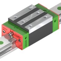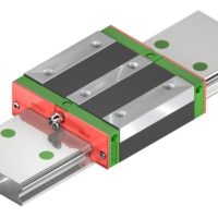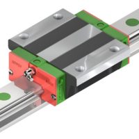
3.1.21 KK86 linear axes with aluminium cover, standard block
66
112
100
90
46
20
86
A – A
87
23
50
28
Ø8h7
Ø46
18
3,5
100
70
13
(n–1) ×100
L1
32
68
6
30
19
200
(m–1) ×200
2 × m–M2,6 × 0,45P × 4DP
Ø50
+0,05
+0
2×n -Ø6,6透,Ø11×6 dp
7、5
B
G
85
L0
4,5
0,5
PCD60
PCD70
4–M4 × 0,7P × 8DP
4–M5 × 0,8P × 10DP
B
1
68
30°
30°
45°
45°
A
4–M6 × 1P × 12DP
116
112
112
75
46
4–M2,6 × 0,45P × 6DP
33,5 8
A
Table 3.18
Dimensions and weights of KK86 linear axes with cover, standard block
Model
Lead
[mm]
L0
[mm]
L1
[mm]
Block A1
Block A2
Maximum stroke [mm]
G
[mm]
K
[mm]
n
m
Block A1
Block A2
Weight [kg]
KK8610P0340
10
340
440
210
100
70
—
3
2
6,5
7,3
KK8610P0440
10
440
540
310
200
20
—
4
3
7、8
8,6
KK8610P0540
10
540
640
410
300
70
—
5
3
9,0
9,8
KK8610P0640
10
640
740
510
400
20
—
6
4
10,3
11,3
KK8610P0740
10
740
840
610
500
70
—
7
4
11,6
12,4
KK8610P0940
10
940
1040
810
700
70
—
9
5
13,0
13,8
KK8620P0340
20
340
440
210
100
70
—
3
2
6,5
7,3
KK8620P0440
20
440
540
310
200
20
—
4
3
7、8
8,6
KK8620P0540
20
540
640
410
300
70
—
5
3
9,0
9,8
KK8620P0640
20
640
740
510
400
20
—
6
4
10,3
11,3
KK8620P0740
20
740
840
610
500
70
—
7
4
11,6
12,4
KK8620P0940
20
940
1040
810
700
70
—
9
5
13,0
13,8
Reference edge
Viewed from the motor flange, the reference edge is located on the left side of the linear axis.
Positioning Syste
m
s
KK Linear axes
144


