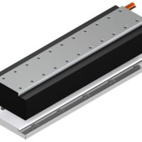
3.1.11 KK50 linear axes with aluminium cover
2 × 2–M2,6 × 0,45P × 4DP
62
55
47
45
25
12,5
50
A – A
40
33
23
12
16
18
26
49,4
35,5
2 × n–Ø4,5Thru,Ø8 × 4DP
74
47
30
8
K
L1
G
5
60
34
14
16,5
10
G
80
A
A
(n–1) × 80
B
19,5
2 × 2–M3 × 0,5P × 4DP
Ø24
Ø5h7
4–M4 × 0,7P × 10DP
L0
+0,03
+0
2,7
6,5
B
45°
45°
0,5
38,5
4–M3 × 0,5P × 6DP
PCD 33
69,3
69,3
Table 3.10
Dimensions and weights of KK50 linear axes with aluminium cover
Model
Lead
[mm]
L0
[mm]
L1
[mm]
Block A1
Block A2
Maximum stroke [mm]
G
[mm]
K
[mm]
n
m
Block A1
Block A2
Weight [kg]
KK5002P0150
2
150
220
70
—
35
80
2
—
1,1
—
KK5002P0200
2
200
270
120
55
20
160
3
—
1,3
1,5
KK5002P0250
2
250
320
170
105
45
160
3
—
1,6
1,8
KK5002P0300
2
300
370
220
155
30
240
4
—
1,8
2,0
Reference edge
Viewed from the motor flange, the reference edge is located on the left side of the linear axis.
Positioning Syste
m
s
KK Linear axes
132


